Equipment Manufacturing Co., LTD")
 Equipment Manufacturing Co., LTD") +86 15853145085
+86 15853145085

 全国服务热线
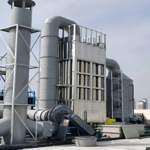
Ⅰ. Flue Gas Characteristics and Treatment Challenges of Quenching Process
High Temperature and High Humidity: The flue gas temperature ranges from 80℃ to 120℃ with a large amount of water vapor.
Complex Components: Contains oil mist (evaporated quenching oil), metal oxides (such as Fe₃O₄), aerosols (0.01-200μm), and VOCs.
High Viscosity: The mixture of oil mist and dust forms viscous pollutants that easily adhere to equipment surfaces.
II. Core Working Principle
1. High-voltage Ionization and Particle Charging Stage
2. Electrostatic Adsorption and Collection Stage
3. Water Film Ash Cleaning and Discharge Stage
III. Complete Technological Process
1. Process Positioning
2. Complete Process Flow
3. Detailed Introduction of Key Process Links
(1) Pre-treatment System (Core Pre-device)
Cooling Treatment: The heat exchanger cools the flue gas from 80-120℃ to 40-60℃, the optimal operating temperature for WESP.
Oil and Large Particle Removal: A cyclone separator is adopted to remove particles larger than 10μm, or a mechanical filter is applied for preliminary filtration.
Humidity Conditioning: A spray tower is used for humidification and cooling to ensure the flue gas humidity meets the operating requirements of WESP.
(2) Main Process of Wet Electrostatic Precipitator
Electric Field Configuration: 2-3 electric fields are connected in series, each equipped with an independent high-frequency power supply, with a total purification efficiency ≥99.9%.
Anode Structure: Honeycomb tubular structure (suitable for high oil mist working conditions) or plate structure (easy maintenance). The materials are 316L stainless steel or FRP.
Spray System: Continuous spraying (0.3-0.5MPa) forms a stable water film to prevent plate scaling; regular high-pressure flushing (0.8-1.2MPa) removes stubborn adhered pollutants. Spiral nozzles are used to achieve full coverage without dead zones.
(3) Wastewater Treatment and Circulation
IV. Special Process Parameters for Quenching Working Conditions
Parameter Item | Recommended Value | Function |
Inlet Flue Gas Temperature | 40-60℃ | Ensure electric field stability and prevent condensation corrosion |
Electric Field Quantity | 2-3 stages | Improve the capture efficiency of fine particles |
Electric Field Voltage | 60-80kV per stage | Ensure effective ionization and particle charging |
Flue Gas Flow Velocity | ≤2.8m/s | Guarantee sufficient residence time (≥2s) |
Spray Pressure | Continuous: 0.3-0.5MPa; Flushing: 0.8-1.2MPa | Form uniform water film and remove scaling deposits |
Plate Spacing | 200-300mm | Prevent discharge breakdown and ensure collection efficiency |
Treatment Efficiency | Particulate matter ≥99%; Oil mist ≥95% | Ensure outlet emission ≤5mg/m³ |
V. Adaptation Advantages for Quenching Process
High-efficiency Oil Mist Removal: The removal rate of quenching oil mist (0.1-10μm) exceeds 95%, which is far better than traditional filtration methods.
Anti-adhesion Performance for Oil Mist: The continuous water film cleans the plates to avoid equipment failure caused by oil dirt hardening in traditional dry electrostatic precipitators.
Strong Synergistic Treatment Capacity: It synchronously removes oil mist, particulate matter (PM2.5) and partial VOCs, and eliminates blue smoke plume generated by oil mist condensation to improve the factory environment.
Safety and Reliability: Wet operation eliminates electric spark risks, making it suitable for quenching flue gas containing flammable and explosive components. The equipment operates stably under quenching furnace load fluctuation (50%-110%).
Resource Recovery: The recovered quenching oil purity can reach 90% to reduce production costs. The water circulation utilization rate exceeds 90% to save water resources.
VI. Application Case
Treatment Air Volume: 20,000m³/h
Inlet Pollutant Concentration: Oil mist and dust ≈80mg/m³
Outlet Pollutant Concentration: ≤3mg/m³, meeting national emission standards
Economic Benefit: Approximately 12 tons of quenching oil are recycled every year with an economic value of about 150,000 RMB, realizing dual benefits of emission reduction and economic income.